By: Patrick Smith

Now on these early systems there was no way for the hydrocarbons to leave the crankcase. It was theoretically recombusted until the output was spent, burnt hydrocarbons. The exception to this was at wide open throttle when the intake manifold had no vacuum to draw pollutants into the engine. At wide open throttle, the engine breathes through the oil filler cap on the filler tube. This was changed in 1966 with a closed PCV sytem on California State cars. 49 State cars gained this set up by 1968. The closed combustion System (CCS) allowed zero hydrorcarbon gas escape. They did it by drawing the pollutants into the engine through suction in the air cleaner element. Let's look further into the General Motors version of closed combustion system, or CCS as it was called.
The basic closed combustion setup: At first glance, there doesn't appear to be much difference between an open PCV and closed PCV system.The main difference is the way the fresh air entrance is rigged. Fresh air enters from the air cleaner into a hose or other connection to the crankcase. The normal route is fresh air entering a PCV filter inside the air cleaner, then going into a hose to the rocker cover. This way it doesn't pass crankcase fumes into the air at wide open throttle. When operating under manifold vacuum, the air flow goes from air cleaner to rocker cover. At wide open throttle, the air flow is by crankcase pressure through the fresh air hose from rocker cover back to air cleaner. Once inside the air cleaner they are sucked into the carb for re entry. With these closed combustion systems you will see a PCV filter at the end of the fresh air hose. Frequent loading up of the filter media tells you blow by is heavy from taking excess fumes.
Transmission Controlled Spark-
 |
| The TCS system when used on Pontiacs, may differ in operation particularly with the way the solenoid is activated. Some years the valve is energized ON, other years energized OFF. Look up the right year to make sure it works correctly, |
In a nutshell, TCS works by having vacuum to the distributor cut on or off by a vacuum solenoid. The solenoid gets current when the ignition switch is on and normally it is fused in with the car fuse block. The solenoid is grounded at the tranny in certain gears and ungrounded in others. One trip up in diagnosing TCS is there are two types of solenoids; normal open to vacuum and normal closed to vacuum. The first one allows vacuum flow when not energized and the second one allows vacuum flow when energized. The earliest set up used normal open solenoids so it would allow vacuum advance at all times should a fuse blow or something happened to break the electrical circuit.
 |
| Top image shows you the transmission controlled spark components found in Pontiacs. The bottom image is of the Combination Emission Control set up found only on Ventura II cars usually with Chevy engines. |
The Pontiac TCS system controls distributor vacuum by an oil pressure sensitive transmission switch connected to a solenoid valve in the carb to distributor vacuum line.Whenever the tranny operates in other than high gear, the tranny switch and solenoid valve are both closed, shutting off vacuum to the advance unit. When the transmissions goes into high gear, oil pressure in the direct clutch circuit causes the transmission switch to open, cutting the signal and opening the solenoid valve, allowing vacuum flow to the unit. A temperature switch allows vacuum to reach the unit below 85 degrees F or above 220 degrees F. With manual transmission cars, the set up is similar but the switch is externally mounted and operated by transmission linkage position.
 |
| A close up of the CEC solenoid and position adjustment. |
Combination Emission Control System CEC:
This set up was used on the Ventura II for 1971 instead of TCS. When the CEC solenoid is energized, the solenoid plunger moves outward against the throttle lever. This speeds up engine and allows ported spark vacuum to the advance unit.It can be energized three ways: a transmission shift into 3rd or Reverse gear, a temperature override switch at temperatures below 82 degrees F, a time delay relay allowing vacuum advance for 15 seconds after turning on ignition during temperatures above 82 degrees F. The CEC solenoid is vented to purge any vacuum that may hold the distributor advanced wen the trans is in 1st or 2nd gear. An idle stop solenoid prevents run on by allowing the valves to close beyond normal idle position when ignition is turned off. That means two throttle positions are required; a curb idle and emission control setting.
The 1971 Thermal Vacuum Switch Set Up (455 HO Engines)
The high output 455 round port engines used a thermal vacuum switch connected to a throttle actuated spark advance. This set up gives no vacuum advance at idle unless engine coolant temperature is above 230 degrees F, when full advance is applied to allow the engine to circulate coolant faster to maintain normal operating temperature.
The 1972 Pontiac CCS System: This year's CCS set up was redesigned.A new Speed Control Spark Advance operation was added by combining bits of the older TCS and CEC set ups. The new acronym for Speed Control Spark Advance is SCS.If it's a four speed manual transmission car, it will be using the older TCS system, If it's running a straight six or Chevrolet 307 V8 it will use the CEC system but without time delay relay.Vacuum advance is allowed 20 seconds after the transmission goes into high or drive gear. Advance is allowed whenever engine temperature is below 82 deg F.
The SCS system has a vacuum advance solenoid valve and temperature sensing switch. The TCS switch is replaced with a speed control spark (SCS) switch. The SCS restricts vacuum spark advance to road speed above 38 mph. The TCS/SCS temp sending switch was moved from the top of intake manifold to the right of the rear cylinder head between plugs 6 and 8. The switch was recalibrated to allow vacuum advance at engine temps below 95 deg F and above 230 deg F. Air cleaner operation is unchanged from 1971.
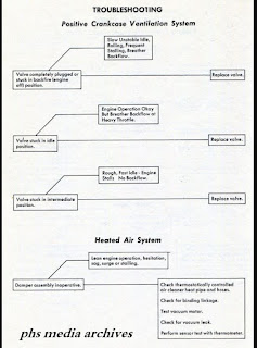
Component Diagnosis: We have included a few flow charts of diagnosis for vehicles with partially imoperative systems. This may help you get the car running for emission testing or help prevent a roadside FAIL from MOE boys.
The SCS system has a vacuum advance solenoid valve and temperature sensing switch. The TCS switch is replaced with a speed control spark (SCS) switch. The SCS restricts vacuum spark advance to road speed above 38 mph. The TCS/SCS temp sending switch was moved from the top of intake manifold to the right of the rear cylinder head between plugs 6 and 8. The switch was recalibrated to allow vacuum advance at engine temps below 95 deg F and above 230 deg F. Air cleaner operation is unchanged from 1971.
Component Diagnosis: We have included a few flow charts of diagnosis for vehicles with partially imoperative systems. This may help you get the car running for emission testing or help prevent a roadside FAIL from MOE boys.
 |
| Although basic, this chart should sort out what parts needs work or replacing. |

Evaporative Control System ECS: There is a purge valve on the intake manifold besides water outlet housing which prevents canister purges until coolant temperature reaches 170 deg F. This makes the exhaust emissions better during cold starts. This set up is not used on Chevy 307 V8s or inline six cylinder cars.
Air Injection Reactor (A.I.R): Some cars due to the State they are sold in such as California, or due to a dirtier camshaft profile, need to run an air pump. The inline six engines use air pumps of the positive displacement vane type. They are belt driven and use a diverter valve, check valve and silencer. The check valve is behind the diverter valve and is a one way diagpragm designed to prevent hot exhaust gas from backing up in the hose and damaging the pump if the belt fails or hose rupture or excessive system pressure. The diverter valve releases air from system during deceleration. It is vacuum actuated.This takes care of the CCS system up to 1973. The following year incorporates a lot of changes and will be covered in a future article.
* Article (c) 2017 by Patrick Smith, images from PHS MEDIA ARCHIVES. This originally
appeared in expanded form on phscollectorcarworldblog April 2017. used with permission.
No comments:
Post a Comment